My resistance to my inner perfectionist, by not shaving the tops off the engine beds, did not last long. I plead extenuating circumstances, which were brought about by the exhaust hose.
The exhaust hose comprises a section from the engine block to the muffler and a section from the muffler to the vent hole in the transom. The muffler must be secured at a lower level than the engine block, because it traps water. If the muffler were higher than the engine, this water could run down into the engine block, rusting the pistons and seizing them. The water trap muffles the noise of the exhaust, and also hinders water from a rogue wave posing water back up the exhaust hose, towards the engine. Ideally, the boat should have a short section of exhaust hose going down from the engine to the muffler, and another, longer, section running up from the muffler to a high point under the cockpit, before exiting through the transom. The high point under the cockpit drains the hose, in case water gets into it. The shorter the exhaust hose, the less water the engine needs to push out, if the exhaust hose gets flooded.
The previous arrangement was awkward, having too much hose and the muffler placed loosely on the floor. The only thing holding the muffler in place was the stiffness of the exhaust hose. Being aft of the engine, it was in a space that is inaccessible to anyone who was neither a dwarf nor a person with six foot extensions to his or her arms. I tried to make the necessary adjustments by reaching over the engine, or wriggling through into the space behind (it was almost impossible to wriggle out again). The required boat-yoga was physically exhaustion and the refitting and fixing the exhaust hose proved difficult and unsatisfactory. In the end, I decided to undo all the bolts and take the engine off its mounts, again.
Having taken the engine off its mounts, I succumbed to my inner perfectionist, took the beds home and shaved off about 12m from the upper surfaces. Now that my hand-plane was razor sharp, this was easier than I had feared. I figured that the rear bearings were wound down to the stops, and the flange plates only just mated, which meant that something was rubbing on something else in the prop-shaft tube. I needed to drop the engine by about 5mm.
I swabbed out the engine bay, again, thinking that this might be the last clean it gets for a very long time, and set about cutting and fixing the hose. The rear part the hose was stiff and reinforced with steel wire, which I did not know until I started to cut it with a hacksaw. The steel wire also explained why I could not push it back onto the spigot on the muffler box. The spigot had an external diameter of 40mm and the hose an internal diameter of 38mm. Brute force would not get them to mate. A spade drill applied to the inside of the hose to ream it out did the trick. The loose ends were secured with hose clamps and the hoses and muffler box were secured with clamps and cable ties. In all, I shortened the rear hose by about one meter, and the forward hose by about 0.5m.
Again, I re-assembled the beds and re-mounted the engine. This, I know, would not be the last time. Gratifyingly, the flange plates met somewhere in the middle of the prop-shaft tube. I had wound the rear bearings up by about 5mm, the reduction of the bed tops and this adjustment giving me the 5mm I was looking for. I adjusted the forward bearings until the feeler gauge told me that the prop-shaft flange and engine flange were parallel and in line.
The reconnection of all the fuel and water hose lines marked the beginning of the end for the mechanical phase and the start of the start of the electrical phase.
I had been procrastinating on the electricals whilst I was sorting the mechanicals. My first engagement was to jury-rig a spare battery to the engine in an attempt to start it. The battery achieved about an eighth of a turn before giving up, needing a considerable recharge, but the exercise demonstrated that the starter motor and solenoid were in working order, but the electrical system in the boat was not.
The two factors that condemned the electrical system were the accumulation of poor initial design, consequent bodge-jobs and quick fixes that culminated in the current rats' nest of wiring, and the episode in which the leak in the shaft seal submerged the inside of the boat to about a foot of sea water. The flooding of the boat did not affect every electrical system on the boat, but, the many switches located near the floor were damaged. I found a tide-mark on one of the batteries showing that the water stopped just a couple of inches below the terminals. The arrangement of switchgear at floor level was a design fault that was pointed out by my surveyor when I bought the boat, together with the absence of anything to hold down the batteries. Also, after spending countless hours baling out water from the bilges, I thought it was time to indulge in an automatic bilge pump.
My intent is to relocate all the switch gear to a new box that will be mounted at about head-height on the bulkhead to starboard of the companionway. This will do several things, including the prevention of further seawater leaks ruining low-lying switchgear. It will make the job of re-wiring the boat much more pleasant, as I will be able to see what I need to do at head-height. It will make the switches much more accessible, and it will provide a protected cavity for the backs of instruments mounted on the bulkhead. Further advantages include improved accessibility to the engine stop-start switches and anchor windlass from the companionway and, possibly, providing a mounting point for instrument panels that I might want to mount on hinges in the companionway (e.g., a monitor screen for a navigation computer). In any case, I like having switches and other electrical items stowed inside the boat when not in use, to protect it from the weather.
Other than getting the engine to start and stop at the flick of a button, the next steps are to learn 12V boat electrics.
 |
| Removing about 12mm from the tops of the engine beds |
 |
| Planing the tops of the engine beds. This exposed several redundant holes that I had drilled in the undersides as part of the assembly process, which I then filled with epoxy resin. |
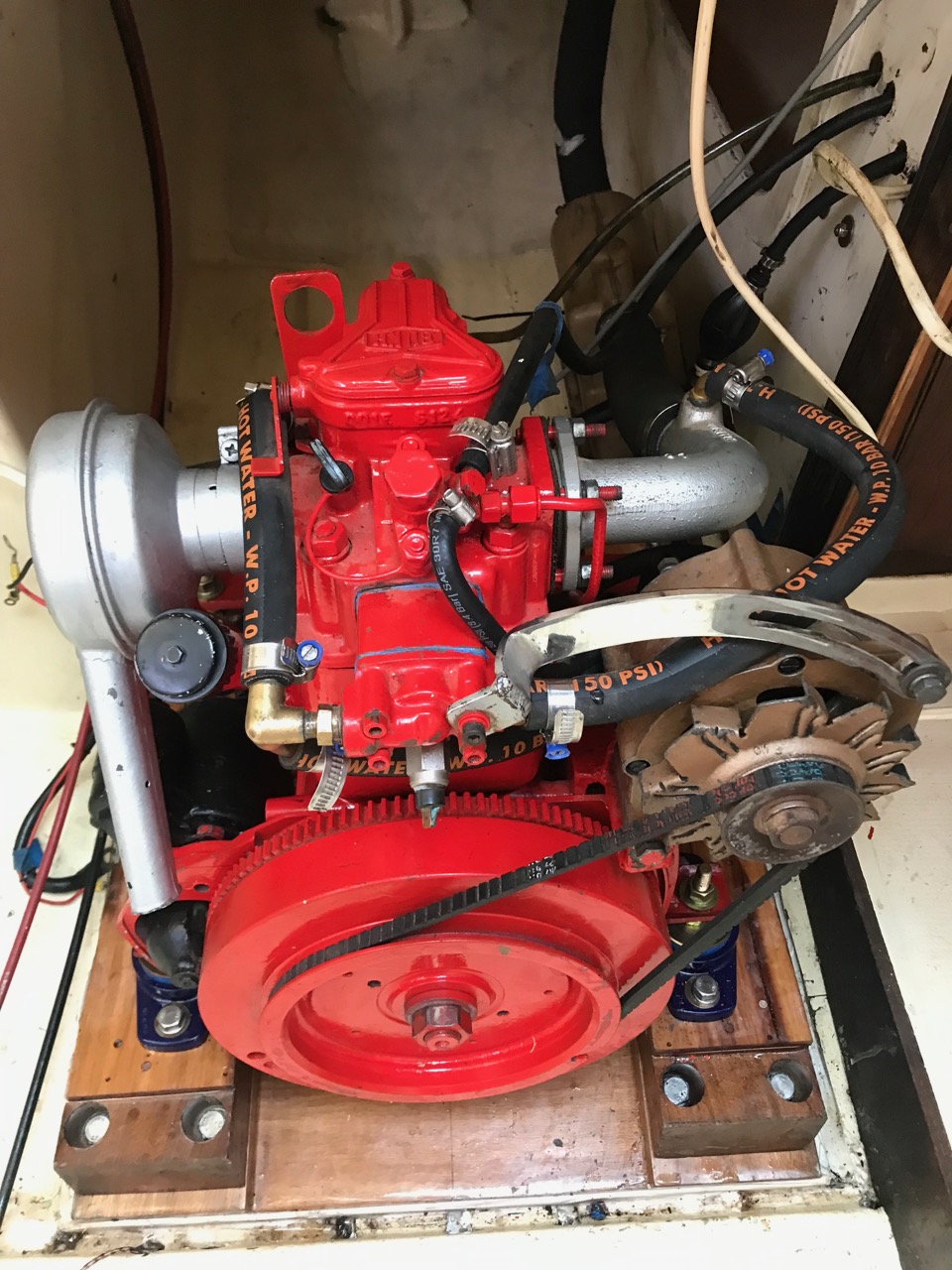 |
| Re-assembled engine |
 |
| Checking clearances - starboard forward bearing |
 |
| Checking clearances - port forward bearing |
 |
| Checking clearances - starboard rear bearing |
 |
| Checking clearances - port rear bearing |
 |
| New exhaust hose arrangement, from engine block elbow (silver colour) to muffler box (brown plastic) to high point under cockpit floor to exit at transom (at rear of boat, not visible) |
 |
| Current electrics around battery terminals |
 |
| Tide mark on battery terminal showing how high the water got when the flange seal leaked. |


