Episode 35 Diesel Engine Part 6 - Fixing the floor plate

One of the skills needed for epoxy work, which is hardly ever mentioned, is the skill to walk away. The temptation is to hover over the uncured epoxy resin like an expectant parent, waiting for it to do something, or, worse, to poke, prod, scrape or to try and shepherd it into the corners that might appear to have been missed.

One of the reasons for constructing the floor plate as a composite of spotted gum planks and epoxy, was to learn this noble skill. There comes a point, where you simply have to walk away, and come back again when the thing has solidified.

I reached that point last Saturday, 20th February, after pouring about 4 to 5 litres of liquid epoxy resin into the gap between the hull and the floor plate. Apart from a minor spill that resulted in a tongue-like glacier of whitish goo creeping into the bilge, it went well, so I gave the operation about 8 out of 10. The glacier was surprisingly easy to remove the next day (I ripped it out with my bare hands). I attribute the ease of its removal to it forming on a puddle in a bilge that had been regularly bathed in oil and diesel fuel for the last few years, thus denying it much of a purchase.

The glacier's lack of tenacity might have got me worried about the bond under the floor plate. However, this was an area that I had cleaned, cleaned, and cleaned again; first with boiling water and dishwashing detergent (which, I had been informed, was as good as any chemical degreaser), then rinsing and swabbing with methylated spirits and, finally, swabbing again with MEK. Also I had previously roughed the surface with a wire brush, to get rid of any loose flakes, and to provide a physical purchase for the epoxy, and followed up with a vacuum cleaner.

I taped over the top surface of the floor plate and sides with clear packing tape. The floor plate and hull were about 6 degrees from the horizontal, so that everything would flow down, forward, towards the bilge. Some of the liquid epoxy would be slightly pressurised under the floor plate, so I needed a good seal to keep it there.

I poured the epoxy into four 13mm holes drilled through the plate at its  higher end, towards the rear. Thinking about how I would get the epoxy into the holes, I hit upon the use of plastic, picnic wine-glasses, which were of just the right shape and size to act as funnels when they had had the bottoms of their hollow stems cut off. They were cheap, which always appeals. They also provided a reservoir to allow the epoxy to flow down and settle, in the way that it does. The four holes ensured that I would get the epoxy into all the places it needed to go.

Finally, I made some rough calculations on the volume needed. I thought I would need about 4 to 6 litres, and had a total of about 9 litres (mixed) to hand. This was based on multiplying the plan area of the plate, which I knew, by the thickness of the join, which I had to guess, based on eyeballing my curved jig and mentally estimating the number of millimetres between the bottom of the plate and the curved hull. Having determined that I would not run out of epoxy half way through the operation, I was set to go. I decided on a 1 to 3 to 2 mix of hardener, resin and nor cells, thinking that I would need a fairly runny mix to get it into all the available corners without leaving voids or bubbles.

When I started mixing and pouring into the picnic wine-glasses my first concern was that the liquid epoxy would reach the bottom end. It did, and I could start to see it filling up through the clear packing tape. Thankfully, to start with, there were no leaks, indicating that my aluminium angle-bracket and filler dams were working.

I worked as fast as possible, hoping to avoid the creation of voids by uneven solidification. When the liquid epoxy showed up at the top end of the floor plate, I knew I had poured enough. However, this was when I noticed the small glacier moving into the bilge. There was nothing I could do - I could not add any more packing tape, because it would not stick to anything touched by the liquid resin. I managed to get some more tape onto what I thought was the offending corner, but in the end I had to convince myself that it was a slow-moving glacier that just had to run its course until the resin had started to set. 

This was the point of walking away.

Returning the next day, I was relieved to see that the level of epoxy at the uphill end of the plate had reduce by no more than about 10mm. The resin was clearly visible in the holes previously occupied by the picnic wine-glasses, which meant that the space between the plate and hull had been filled. The upper, outer corners under the plate might not be completely filled but that would be a minor flaw.

The next steps will be to clean up, and then to start the difficult task of measuring up for the wedge-shaped engine beds. 

Floor plate coated liberally with clear epoxy resin top and bottom, before installation. I decided on a clear coat so that, if the plate were ever to rot, it would be visible. It also makes the construction material plain to see.

Exposed hull cleaned and ready for the fitting of the floor plate. I had made small dams out of filler either side of the flange plate to catch any water seeping into the area.

Last checks for clearances, using the model of the underside of the engine at, hopefully, the right angle. It looks good to go.

Picnic wind-glasses in place, jammed nicely into the holes drilled through the plate. Top and bottom lined up to the marks. This is the point of no return.

The end of the pour, showing the glacier of goo creeping into the bilge. The strings were a last-minute, ultimately successful, attempt to stop the mousing lines from sagging into the liquid resin. I am using the engine flywheel as a 17kg deadweight to weigh the floor down.


Episode 34 Diesel Engine Part 5 - Construction of the Floor Plate

The construction of the floor plate has to be the most geometrically challenging project I have ever undertaken. It has consumed countless hours over the past two months, and I have been working on it more than the engine. If I were doing this at work, I might use 3D laser-scanning to create digital twins that I could play with, tossing them around weightlessly, cutting holes and filling gaps with ease on the computer screen. But, I am doing this at home, which means using the analogue prototypes of hull and engine, and slowly figuring out how to join the one to the other.

The floor plate’s first function is to provide a strong platform, glued securely to the hull with epoxy resin, onto which I can bolt the engine beds. The hull is curved, and the engine beds will be made of wedges, cut to the right angle between the axis of the engine and the hull. The second function of the floor plate is less obvious, but just as important, which is to provide the reference surfaces and planes from which I can take the measurements for the engine beds.

The construction of the floor plate used 20 pieces of spotted gum 19mm floor planking, assembled in four layers, joined with birch dowels and epoxy. I also made up several jigs to measure things and to act as guides to the cutting operations.

I chose spotted gum because it of its density, strength and durability, or resistance to rot, according to the New South Wales Technical Publication Series 5 Timbers in Boat Building. Another reason is that it is available as machined flooring planks. Given that I would be assembling the floor plate in my own garage, I thought it would be better to start with something sawn to machine-grade tolerances. The floor planks also meant I could build up the layers with the grain criss-crossed, like plywood, increasing the strength of the composite construction in all planes.

I used Norglass Epoxy with Norcells as a filler or extender. The slow hardener gave me more time to get things positioned, and allowed the epoxy to run into all the cracks and voids it could find, reducing the opportunities for water to get into the timber. I had also tested International Epiglass, but it cured faster and gave off considerable heat, which might have stressed the composite construction. Before gluing I wiped down the surfaces with Methylated Spirits and then MEK paint thinner. Fun fact; MEK dissolves some types of plastic gloves.

Another aspect of this approach was that it built up my experience of working with epoxy resin before the Big One, which would be pouring the epoxy into the join between the floor plate and hull; a daunting point of no return and something that had to go right the first time.

Typically, I mixed the hardener, epoxy and Norcells in the ratio 1:3:4 by volume. This yielded a white paste with the consistency of runny custard. Liquid epoxy has no surface tension, unlike water, and if it finds the tiniest crack, it will find a way through. It does not run fast, but it does run far. I found a friend in clear packing tape, which would stick to the timber, but deny any adhesion to the cured epoxy. I became adept at constructing packing-tape dams around my assemblies to stop the liquid epoxy dribbling down the sides. 

My experience with the runny-ness of liquid epoxy portended a potential problem with the gluing of the floor plate to the hull. If the hull were horizontal, life would be easy, but it is not. It is at an angle of about 6 degrees to the horizontal, meaning that any epoxy I pour into the join would simply run out of the downhill side, forming an immovable puddle of useless gunk in the bilge, forever fixing whatever it touched permanently in place, except, of course, the floor plate. I built a dam around the outside of the floor plate with extruded aluminium angle, sealing the remaining gaps with Parfix gap filler. The addition of packing tape should keep the liquid epoxy in place until it has set. I will report back on this operation, when it is done.

The assembly of the spotted gum planks took several weeks, including an afternoon with my mate, Naman, and his tools to get the sides trimmed and squared up. He is a furniture-builder, and went to town on getting the angles right. It was interesting watching him work. Like other craftsmen, he would take perhaps 15 to 30 minutes setting up a cut, the cut itself being quite brief. No wonder Leo has spent the last four years restoring and rebuilding the classic sailing yacht Tally Ho (I watch his YouTube episodes religiously).  The last thing I asked Naman to do was to route a scoreline along the centre for reference. I told him not to fuss too much about the bottom surface, because it was about to get hacked. When I got the plate home, I shaped the curved base with the wanton use of a belt sander, checking it with a jig to mimic the curved hull.

Having got the base of the floor plate to mate with the hull, I measured the dimensions for the top surface. This is where I needed my measuring-jigs. There are no published dimensions for the engine or its mounts, so it was a case of measuring what was there and transferring the dimensions to the floor plate and my measuring jigs and guides. 

However, one cannot simply measure the dimensions between the bearings on one side to the other. The engine is in the way. Also, it is impossible to measure the height of the engine sump from the floor, because the underside of the engine has an irregular shape, and the whole thing is at an angle. My most recent jigs include a positive template of the underside of the engine cut into a piece of pine (the negative came from a breakfast cereal box), and sawing guides, cut at the right angle (hopefully) to the floor plate. With these two jigs with the shaft flange as a reference, I estimated the clearances under the engine, and hence the angle and dimensions of the slot cut into the top of the floor plate. 

I might have overthought it a little, but in anticipation of this slot, I glued the lower layers of the spotted gum sideways, to reduce the exposure of end-grain to a potential source of water from the shaft seal. These sideways-on pieces provided extra strength to the longways-on pieces, as I cut through the upper layers. The last dry-fitting on the boat showed me that I had got the angle wrong, and I needed to cut the slot deeper to ensure sufficient clearance to the underside of the engine, allowing for its biggest vibrations. I don’t know exactly what clearance is sufficient, but I reckon that if I can get the tips of my fingers into the gap (about 10mm), it should be enough, even allowing for the inaccuracies in my measurements. Deepening the slot with my circular saw left a couple of accidental gouge marks that might need to be filled. The filling is mainly cosmetic, but I worry about the opportunities that the water might take to get into the grain of the timber.

The photos show the completed floor plate. The handles are temporary, allowing me to lift the 16.5kg thing and jiggle it into place on my work bench and in the bowels of my boat. What remains are some final checks, some coats of epoxy or varnish to seal the surface, and a thorough clean of the hull. Finally there is the scary job of gluing it in place with only one chance to get it right. Once it is in there, it is never coming out.


Underside of floor plate. The jig at the back mimics the curvature of the hull.

Topside of floor plate following its squaring up by Naman.

Perimeter dam around hole in floor, made from aluminium angle, to stop the liquid epoxy running  away.

Negative of underside of engine, made from a breakfast cereal box.

Transferring the negative onto a positive template of the underside of the engine.

Saw guides, used to cut the slot into the top of the floor plate.

Chiselling out the slot. The chisel set originally belonged to my great-grandfather, who was a merchant mariner, probably used for his apprenticeship.

Dry-fitting the floor plate with the engine template.  This shows that there is insufficient clearance, meaning that the slot needs to be made bigger.

Using new cutting guides and the engine template to test the larger slot for  clearances. This time, it looks OK.

The finished floor plate, looking at the rear. When the floor plate is in the boat, we would be looking forward. The slot accommodates the gearbox and flange, so that the flange can be fitted to the prop shaft. The handles are temporary, but are jolly useful in moving this thing around.


Episode 33 Diesel Engine Part 4 - Paint, Acid, Limescale, Thermostats and Anodes

The good thing about paint is that it covers everything in a nice glossy coat. The bad thing about paint is exactly the same - it covers everything, including the parts you might want to see. This seems to me to be something of a disadvantage when, for example, you are trying to figure out what lies beneath. In this case, I needed to take the thermostat assembly apart to fit the new thermostat that had finally arrived from The Engine Room. 

It took longer than the 2 to 6 working days, that I had paid for, to ship the new parts from the Auckland to Brisbane. The Engine Room had placed the order on 30 Dec 2021 and the parts arrived on 19 Jan 2022, which, by my reckoning, is  at least 12 business days, depending on how you count public holidays. Yes, I know it was Christmas, and COVID etc. but of all people who should know how these things affect their business, it is the couriers, and they should advise accordingly. I don’t blame the Engine Room, but I am miffed about not getting what I paid for, in terms of delivery time.

When I took delivery of the rebuilt engine from Diesel Works, it had come in its shiny new coat of paint, but with the thermostat removed. You can see the old and new thermostat and engine elbow in the photo below. It is obvious that the old thermostat was cactus, and had been so for a while.

I needed to take the newly re-assembled housing apart, so I could insert the new thermostat. This is where I got to the problem of paint. Bukh, along with other engine manufacturers, uses many different metals in the construction of its engines. Some parts are softer than others, which makes them more vulnerable to spanner-wielding amateurs, like me, than other parts. The problem with paint is you don’t know which part is made of what until you take it apart. Also, when a part of one type of metal is screwed into a part of a different type of metal, you get the corrosion caused by dissimilar metals, which is especially problematic in a marine environment. I found a good example of this when attempting to remove the old brass barb from the old stainless steel exhaust elbow. There was so much corrosion product in the joint, that I practically destroyed the old barb trying to unscrew it, hence, the hasty addition of a new barb to my shopping list from the Engine Room (the old and new barbs are included in the photo below).

With softer metals, such as brass, you can easily round off the nuts or strip the threads when taking components apart. Some of the parts for the thermostat housing took some persuasion to shift, hindered by the awkward arrangement (what my mate rightly calls “awkwardosity”) of the corrosion-welded components. I resorted to ingenious and unrepeatable combinations of the bench vice and adjustable spanners to grip the part and a large shifter to turn the housing.

Further problems arose from the accumulation of lime-scale inside the assembly, which contributed to the melding of parts that should not have been melded. The Bukh DV10 LME, like the others in its family, is cooled by seawater. It sucks water from the ocean, pumps it around the cylinder block, and pushes it into the exhaust elbow from which it gets blown back into the sea via the muffler and exhaust pipes. The rate of circulation around the cylinder block is controlled by the thermostat. When you heat or boil seawater you are left with a number of residues, including limescale, which is the same stuff that goes into making cement. Limescale, being alkaline, can be removed by an acid.

Being rather fussy about cleaning things before putting them back together, and also needing a clean seat for the new thermostat, I decided to clean the parts in an acid bath. Initially, I was concerned that the acid would eat not just the limescale, but also the parts themselves. After some tentative trials and research, I settled on a concrete cleaner from the local hardware store, because it was mainly Hydrochloric Acid, was relatively cheap and came in a 5 litre bottle. I reckoned on quantity rather than quality, as I did not know how my parts would react. I found that the acid ate the limescale, leaving the metal and paint in tact, so I put the parts in for a soak over a couple of nights to shift the limescale cement and other gunk. The acid might have eaten some of the parent metal, but it was difficult to tell. I thought the loss of any parent metal a fair price for a clean seat for the thermostat, and a general clean out of the tubes.

The acid bath and cleaning revealed that the connectors were brass, the thermostat housing body was copper, and the top piece, which connected them together seemed to be a composite construction with a copper skin and an alloy body. I say “seemed” because it is not clear whether the surface I was cleaning was residual limescale cement, or parent metal. Or something else.

In the disassembly process, the paint to the connections took a bashing. Rather than repaint them, I decided to clean off the paint completely. I like the look of the brass. I know it will not stay this clean and shiny but, in future, it should be obvious that it is a brass fitting, deserving of more care than, say, cast iron.

I reassembled the thermostat housing with new gaskets and replaced the old, crimped water lines. A new set of gaskets from Bukh costs and eye-watering $700, which is way too much to consider every time you need to take off the thermostat housing, or something else. I would only consider a new gasket set if I were to disassemble the cylinder head, which is unlikely. I bought some gasket paper and Permatex Ultra Blue (gasket goo) from the local Auto Shop, and cut out some new gaskets for the thermostat housing with a sharp knife and nail scissors. The fellow in the shop assured me that the paper and goo was good for water, as well as oil.

I also found that the metal used to crimp the water and fuel lines was quite soft, possibly lead or alloy. I needed to remove the crimping and the old lines from the banjo bolts so I could re-use the latter. The crimping yielded to some attention from a wire cutter, leaving the banjo bolts mostly unmarked.

The ambiguous interface between parent metal and limescale resurfaced when I poked around with the engine anode. The anode is, or should be, a removable bolt with a sacrificial zinc body screwed into the end. Provided the zinc is electrically connected to the engine, the seawater cooling water will eat the zinc in preference to the engine. Because of its sacrificial nature, the anode needs to be replaced regularly. Unfortunately, a previous owner appears to have foregone the replacement of the zinc anode, electing instead to screw in a plain mild steel bolt with no visible zinc. The mild steel bolt is 14mm diameter with a 22mm nut on the end and it had been shorted by the addition of a nut as a washer on the outer surface. It also has a copper washer. 

When I removed it, I could see how far the bolt protruded into the coolant gallery around the cylinder head, but was unsure whether the far end of the hole was parent metal or an accumulation of limescale cement. The replacement pencil anode that I had bought was a cylinder with a diameter of 12mm and a length of 37mm, specifically marketed for Bukh engines, but I could only insert it 25mm into the hole, which was the length of the old steel bolt. The question remained about whether I had reached the end of the “real” hole, or if the end had been blocked up with limescale cement. There was no way of telling, without drilling it out. However, if I drilled it, I risked drilling all the way through the wall of the cylinder block, which would kill the engine with certain death and write off the money I had spent on it. 

With the help of a mate, Bill and his pillar drill, I cut off the end of the old bolt, drilled and threaded a hole into the end, screwed the new pencil anode onto the bolt and sawed off the excess length. It was galling to reduce the zinc cylinder from about 37mm to 12mm to get the assembly to fit into the hole. At least I had an engine anode, where none existed previously. Further, I now the means to replace it frequent intervals.

I am now seeking some advice, from anyone who knows, about how deep the anode hole should actually go. My cut-down anode will work, but may need replacing at frequent intervals. It would be nice to be able to insert a full length anode, and leave it longer.

(CORRECTION - I had previously referred to this engine as a Bukh DV10 LSME, but it is, in fact, a Bukh DV10 LME. The "S" is the sail drive version, which this is not).

Old and new replacement thermostat, exhaust barb, exhaust elbow and exhaust gasket.

Old and new replacement thermostat, exhaust barb, exhaust elbow and exhaust gasket. The jagged hole in the old exhaust elbow occurred from previous attempts to fix it.

Example of old water line with crimping. The banjo bolt housing, to the right, needs to be saved for re-use.

Thermostat housing at start of disassembly, showing the gaskets. I'm holding the housing upside-down, by mistake.

Reassembled thermostat housing with new water lines. The blue is excess gasket goo.

Reassembled thermostat housing with new water lines. The blue is excess gasket goo.

Old bolt from the anode socket.

Modified bolt with shortened pencil anode screwed onto the end

Episode 32 - Diesel engine Part 3 - Interrupted by water

The scariest thing about this project is not knowing quite everything about what keeps water out of the boat.

The glass reinforced plastic (GRP) hull is easy, and the stopcocks are not difficult to figure out. The shaft seal, however, was a mystery. It turns out that that the type of seal on my boat is a PSS Shaft Seal, installed when I replaced the shaft and prop in 2019. Normally, access to the seal is by the usual contortions and boat yoga performed over the engine, which is not designed to comfortably bear your full body weight, transmitted through the softer regions of your belly, whilst you try to get your hands to the seal.

The PSS Shaft Seal website has an interesting graphic that tells most, but not all, of the story. What is not immediately obvious to the uninitiated is that the bellows (the black wriggly rubbery section) are fixed to the boat and all they do is push the sealing ring (the part with the small pipe coming out of it) against the stainless steel collar (to the right of the assemblies shown on the website). The stainless steel collar is fixed to the prop shaft which, of course, rotates. The joint between the sealing ring and stainless steel collar keeps the water out of the boat.

The pressure holding the sealing ring against the stainless steel collar is quite light; it only needs to resist about 0.3m (1 ft) of water pressure, so it does not need a lot of pressure to keep the water out. It is not difficult to dislodge (I’ll return to that, shortly), but is usually kept safely in position by the engine. 

Another important feature is the small tube coming out of the side of the sealing ring. This is to allow air in the seal to be “burped” out, by squeezing the bellows. If you don’t “burp” the seal, it will drip. An air bubble in the seal is enough to crack open the joint between the sealing ring and stainless steel collar. You need to burp the seal every time you put take the boat back into the water, or it will drip.

With no engine to keep things in place, the shaft is vulnerable to getting knocked about, especially when you are trying to cut away engine beds with a demolition saw in close proximity. Many times, I dislodged the seal, letting water in, but it was relatively quick and easy to re-seal it with a bit of a wiggle. 

Religiously, or so I thought, I would not leave the boat unless I was satisfied that the seal had been seated nicely so that it would not leak in my absence. I even devised a little cradle for the prop shaft so that it was not resting on the bottom surface of the shaft tube. The timber got painted red from my engine-part respraying exploits, and you can see it in some of the photos under the prop flange.

However, alas, I either let my guard down, or something happened in my absence to dislodge the seal. I left the boat on Friday afternoon, confident that it would stay dry, and got a call from the marina on Tuesday morning to say that the boat was taking on water and was lying about 1 foot lower than it should. Phil from the marina politely asked if he could open the boat to drop a couple of pumps in there to pump it out. Politely, I responded yes please, and privately started to worry about where the water was coming from, and whether I should try to get the boat on the slip (which was closed for Christmas) in a hurry.

As I live only about half an hour from the Marina, and was working from home, I clocked off for lunch and hied on down there as fast as the legal road speed limits would allow. The pumps had done their job and the boat did not sink. It was wet, though, and the prime suspect, a the dislodged shaft seal, was burbling away merrily, trying to sink the boat anew. With a bit of a wiggle, I re-seated the seal and set about cleaning the boat (again) and mopping out the bilge (again) and wondering if I should get an automated bilge pump, and where I could possibly put it. I did not dare to switch on the electrics, but it is possible that the water reached to the lowest of the switches in my switch panels. I remembered that my surveyor had mentioned something about the disadvantages of having switch panels mounted low down. I will need to rewire the engine connections in any case, and this water ingress might precipitate a more comprehensive rewiring project.

Phil suggested I put some tape around the seal to keep it safe. One of the advantages of volunteering with the SES is that you learn some useful stuff, like what tape is useful for what. In this case, I did not want something that stuck like superglue to the more rubbery parts of the seal, because it might damage it when I pulled it off. In any case, residual glue on the parts would attract dirt and the ever-present boat-crumbs that seem to spontaneously regenerate in the bilge. I needed something that was moderately water-proof and that would not stick to anything but itself. The worst solution was gaffer tape; the best duct tape. Fortunately, I had a small roll of duct tape at home, and dutifully applied it to the seal. I checked the boat over the next couple of days and was glad to see it bone dry (again). I also removed all the clutter I had left in the boat, including all the cushions, to take them home to dry them. In the process, I found some lockers that I did not know I had, and some stuff in the lockers that I did not know I had, including a spare jib-track car. I had previously tried, and failed, to find a replacement for the broken one on deck, and had started to buy the (expensive) parts to replace not just the cars, but the tracks also, because the new cars do not fit the old tracks. In the end I gave up, returned the parts to the shops I had bought them from, and set a block up on the toe rail for the jib sheet as a jury-rig.

There are some lessons to be learned here;
  • Berthing in a marina is expensive, but cheaper than finding out that your boat has sunk while you were away. I am very grateful to Phil and the others at the marina for keeping an eye on my boat and all the others in the absence of their owners.
  • When doing major surgery to your boat, it is a good idea to empty it of everything that is not screwed down. I had to get everything out for a clean and a dry part way through the project, and might have made life easier for myself by doing it at the start. It would have meant less cleaning, especially to the cushions and other soft bits and pieces, such as the life-jackets.
  • If your shaft seal is dangling around in mid-air, secure it with a little chair and tape it up with duct tape.

Finally, I will probably get an automated bilge pump. The question is not about expense - the cheaper ones are about $50. The question, in my case, is that the bilge is so shallow that there is not enough headroom under the floorboards to get an off-the-shelf pump in there. The maximum headroom under the floorboards is just about a hand-breadth (not including my thumb), or about 80mm, which is less than the 125mm needed for the smallest pump units. Possible solutions are a pump with a remote sensor and suction tube (not available off-the-shelf), or taking out a section of the cabin sole in the engine compartment under the cowling, or cover, that sits over the engine. Another conundrum to solve, and the list just gets longer!

Phil from the marina took this photo after he had started to pump the boat out


Episode 31 - Diesel Engine Part 2

Sub-projects

The overhaul of my diesel engine is, in fact, a number of sub-projects run roughly in parallel. Some of the sub-projects, such as the rewiring, cannot start in earnest until the earlier projects have been brought to some sort of conclusion, if not to completion.

Another such sub-project is the rebuilding of the engine beds, which I had delayed until I had confirmed that the old diesel engine would go back into the boat. A new engine might have required an entirely new bed configuration. 

The engine beds are the two parallel beams on which the engine brackets and mounts sit, as shown in the first photo. As the engine lay not horizontally, but on the same plane as the propellor shaft, the engine needs only four brackets and mounts. If the engine were laid horizontally, it would need six brackets and mounts and a universal coupling between the gearbox and shaft. 

Finding the angle of the propellor shaft proved more difficult than I had expected. If the boat were out of the water, it would be quite simple; all I would need to do was to remove the propellor shaft from its tube, shoot a string line or laser through the tube into the boat and mark where the string line or laser would hit the mast or a bulkhead (it would hit the mast unless the boat was seriously out of whack). However, removing the shaft means breaking the shaft seal, which means that any water outside the boat would rapidly find its way inside the boat, sinking it quickly. Whilst the boat was in the water, all I had to work with was the existing beds and the near-vertical face of the connecting flange, which is about 90mm in diameter with a hole in the middle.

After much measuring with inclinometers, and the usual boat-yoga needed to read the numbers, I found that the rear part or upper step of the existing beds was probably on the right plane, about 5.5 degrees from the horizontal. The absolute angle was not important; what was important was getting a reference line inside the boat for the new beds. Furthermore, after yet more boat-yoga, and several measuring jigs, I determined that the rear part or upper step of the existing beds was also the right offset from the plane of the propellor shaft for the new bearings.

The geometry is incredibly complex, and difficult to describe in words. The difficulty in measuring things was made harder by the absence of reliable reference lines or planes - almost nothing was straight, flat or with nice sharp edges to measure from. I went through half a dozen measuring jigs, just to get the fundamental dimensions.

What I found was some shoddy workmanship in the original build. Although the rear part or upper step of the beds had been set properly, the front part or lower step was set at the wrong angle and it was too short, requiring the builders to bolt on an additional 2 inches of timber just to provide enough material to screw the mounts to. The second photo below might be a little hard to read because I traced both port and starboard beds onto the card as a rough reference. The black lines show what is actually there, and the thin blue line shows what is needed. The wrong angles on the lower front steps might have contributed to the snapping of the forward starboard bracket under the started motor, which has now been re-welded.

Furthermore, as I probed into the construction of the beds themselves I found what amounted to a heap of timber off-cuts, including soggy pine, with plenty of air voids and globs of un-bonded resin. I had hoped to saw off the tops of the beds and replace the surfaces on which the engine bearings sat, but there was not enough sound timber or glass, and what was left was unusable. The third photo below shows the beds partly removed with my battery-powered demolition saw (my new favourite toy).

I could not tolerate the shoddy work and resorted to cutting out beds entirely. To give you an idea of the state of things, I removed most of the timber off-cuts in the beds by ripping them out with my bare hands after some initial attention with the demolition saw, such was the poor state of fixing and bonding under the hull. I worked with my hands as much as possible, taking care not to send the demolition saw through the boat hull, for obvious reasons. I did not even need a hammer to dislodge the timber off-cuts.

After the initial removal of the beds, I saw what I thought to be a crack in the hull, which might have beed caused by a grounding by a previous owner. I cut out more of the floor and cleaned it up to find that the crack only extended to a superficial layer of spilled resin and did not extend to the hull. To my great relief, the hull itself appeared in perfect condition with no cracking whatsoever. 

Whilst investigating the crack, I emailed my insurers to ask advice. When I had established that the crack did not extend to the hull, my insurers acknowledged my diagnosis and suggested that I keep a photographic record for future reference. Incidentally, my insurers also informed me that the crack (or something similar) could only trigger a claim if it were related to an identifiable event. Shoddy build-quality was not covered. In any event, it was advisable to inform my insurers about the work I was doing.

One more job was to give the bilge a good clean, which I did with dishwashing liquid, a scrubbing brush, and a garden hose on “jet” setting, followed up with swabbing the exposed hull with methylated spirits. Given that the main driver for this project was to de-smell the boat, I used the opportunity of an exposed hull to remove as much as possible of some 40 years’ accumulated oil, grease, grit, resin spills and generally smelly muck. The resulting bilge soup filled four 10-litre buckets with filth, and went into the disposal tank at the nearby slips. It is not a job I would like to repeat. I’ll clean the hull further when I get to gluing or epoxy-ing the new floor into place. For every hour of measuring and cutting, I must have spent another hour of cleaning up.

The final photo below shows the engine bay after the removal of the beds and floor, after initial cleaning. 

I will address the rebuilding of the beds in a consequent blog.

Critical dimensions

I found these by measurement, as there appear to be no record drawings in existence

  • Diameter of propellor shaft = 1 inch (25.4mm)
  • Diameter of propellor shaft tube (found by wiggling the shaft from side to side and up and down) = about 35mm, which means the shaft is central in the tube when it is 5mm from either the left-right or up-down limits of wiggle. 
  • Amount of fore-and-aft wiggle in the shaft = 10mm. At rest, the water pressure on the outside of the propellor shaft pushes the shaft forward until the propellor rests on the P-bracket at the rear of the boat, This also extends the seal inside the boat. This means I will need to arrange the engine so that it pushes the shaft backward by 5mm, getting the propellor clear of the P-bracket, and so that the seal is not fully compressed.
  • Additional length of shaft due to polyflex coupling = 25mm. This means I will need to align the engine so that the flanges touch, mark it off, then move the engine forward* by 20mm to allow for the addition of the poly flex coupling and the 5mm adjustment mentioned above.
  • Diameter of polyflex coupling = 127mm. This means I will need to ensure that the new floor is low enough to not touch the polyflex coupling, which has a larger diameter than the original flanges.
  • All four engine mounts are in the same plane, unless the rear mounts are mounted upside-down, which was the case with my engine. If the rear brackets are mounted upside-down, the beds need a step of 85mm.
  • Offset from plane of propellor shaft to underside of mounting bracket = 19mm (maybe 20mm?)
  • Offset from plane of propellor shaft to underside of new mounting bearings = 66 to 90mm. This means the mid-point is about 75mm, which is the offset to the existing bed. The upper limit of 90mm allows for some of the adjustment stud to remain exposed, which is needed because the stud has flat surfaces for gripping the top end for tightening the nuts.
  • Minimum dimension between inside faces of beds = 300mm
  • Minimum width of beds = width of new poly flex bearings = about 85mm
  • Maximum dimension of outside faces of beds = about 465mm.
  • Fore-aft dimension for new floor plate = 510mm
  • Athwartships** dimension for new floor plate = 570mm
  • Versine of hull curvature over 570mm = about 20mm

* Forward means towards the front end of the boat, which can be confusing as you spend all of your time on the engine looking towards the back end of the boat. So, moving it forward generally means pulling it towards you.

**I'm using a lame excuse to use the word, which is basically the left-tight or port-starboard direction


Engine beds and floor at start


Tracing of bed profiles. Thick black shows what was there, and thin blue shows what should be there


Beds part way through removal, showing timber off-cuts and air voids under the fibre-glass outer skin


Exposed hull after removal of beds and floor

Episode 30 - Diesel Engine Part 1

For the last year, the biggest question for me, as far as the boat was concerned, was what to do with the diesel engine. Should I recondition it or replace it?


The engine had slowly dripped oil since I had bought the boat, a Cavalier 28 called Bolero, in October 2019. It was a known problem and, rather than being fixed, it had been accommodated by placing a paint tray under the engine to catch the drips. Last Christmas (2020), the engine began to slowly drip diesel fuel. Again, I accommodated the problem by turning off the tap to the fuel hose after every trip, and emptying the paint tray under the engine at more frequent intervals. 


The actual leaks themselves could not be classified as an emergency; diesel fuel is not as volatile as petrol or gas, and it is not easy to light it, but it is not good to allow the situation to continue. More importantly, the smell and the worry of growing puddles of flammable liquids down below kept the Admiral off the boat. Something had to be done.

The engine was a single-cylinder Bukh DV10 LMSE with an external flywheel. As far as I could determine, it had been installed in the boat when it had been built in 1984, so it was almost 40 years’ old. I was faced with the following options.

OPTION 1 - Do Nothing and sell the boat

Pros: This is, obviously, the cheapest option with the added potential of inflated prices in the market as folks spent their money on COVID toys, including boats.

Cons: This would leave me with no boat. The inflated market meant that I would need to spend more on a new (used) boat, with the risks that the new (used) boat would have its own list of expensive and difficult problems. In any case, Bolero, is a nice boat with a reputation for competing well in races and it is perfect for what I use it for - mainly day-sailing in Moreton Bay with family and friends. It would be difficult to replace.

OPTION 2 - Replace the engine with a new engine

Pros: There would be no question of the engine problems being fixed, including the replacement of the rats’ nest of wiring that had evolved around the current engine. The new engine would be an upgrade from my current 10HP to something with a little more power, and would come with a ready supply of replacement parts. I got quotes for two engines that would fit my current drive-shaft and propellor

Nanni N2.14 - about $9600, including GST, engine, mounts, exhaust elbow, wiring and controls. The N2.14 is a two-cylinder 14HP engine with a heat exchanger

Beta 16 - about $9800, including GST, engine, mounts, wiring and controls. The Beta 16 is a two-cylinder 16HP engine with a heat exchanger.

NB: When choosing a new engine, you need to take the propellor into account. The style and pitch of the propellor needs to be matched to the working or maximum revolutions per minute (RPM) of the output. In my case, the propellor had been designed for the Bukh, which spun at a maximum of 3000 RPM. Because the boat came with a worn flappy, folding propellor, I replaced the propellor and shaft in 2019 for about $1500. The Nanni and the Beta would both spin up to 3600 RPM, which was still within the performance curve of the new Bruton folding propellor, and I was loathe to replace the prop with another replacement.

Having got the prices for the Nanni and Beta, I “rounded up” the budget to about $15K with a generous allowance for unforeseen work, which might include major surgery to the engine beds, slipping and specialist trades. I found this difficult to justify, as it was approaching 3/4 of what I had paid for the boat (in a private sale). As a comparison, I recently noticed another Cavalier 28 for sale with an asking price of $40K. 

Cons: This is, obviously, the most expensive option. There were also residual, unavoidable risks in fitting the new engine to the boat, though the wrights would do a proper job.

OPTION 3 - Repair or recondition the Bukh

Pros: Likely to be cheaper than a new engine with fewer risks of fitting it to the boat.

Cons: Replacement parts would be difficult to find. No increase in power (it would stay at 10HP). Risks of finding un-fixable problems.

Regarding the power, I thought it would be nice to have a little more grunt. But, the current engine was capable of 5 to 5.5 knots on flat water (e.g. getting in and out of harbour, and motoring on calm days). The previous owner had claimed that it would do 3.5 knots into a chop with a dingy in tow. The latter case would not be comfortable or pleasurable, but it would likely be the worst conditions I would sail in. Incidentally, I found that maintaining a clean bottom and a clean prop makes a big difference to boat speed, and for about $130, I could hire a diver to give the bottom and prop a scrub. There is more than one way to skin this particular cat.

The Bukh DV 10 LSME is cooled by direct salt-water injection, meaning that it sucks seawater straight out of the sea, circulates it around the engine-head and injects it into the exhaust elbow. It has no heat exchanger. There was no way of telling what damage had been done to the internal galleries around the engine-head by hot saltwater and calcium deposits.

Bukh engines are also remarkably primitive; deliberately so to increase their reliability for the lifeboat engines that Bukh manufactured. The Bukh DV 10 LSME has an external flywheel and mechanical injection. This means you can hand-crank the engine and run it with no electrical inputs whatsoever. The flywheel has a fitting for a starting chord. As an engineer by profession, I am instinctively drawn to the as-simple-as-possible solutions.

The Bukh DV 10 LSME is a rare beast, nearing extinction. Only about 100 or so ever built and it is now out of production. As I was to find out later, the number of replacement exhaust elbows has dwindled, and I was lucky to find one of only two known replacements in the Southern Hemisphere.

The remaining risks with this approach were to do with the engine beds, which looked shonky, the wiring, controls (which were well-worn) and peripherals, such as the exhaust elbow.

OPTION 4 - Replace the diesel engine with an electric motor

Pros: Quiet engine with no smelly oil or diesel fuel.

Cons: Cost. Although an equivalent electric motor would cost about the same as a diesel motor (say $8K), the batteries would cost several hundred tanks of diesel fuel. My current diesel consumes about $3 to $4 of fuel per hour. It might even lose more fuel to leaks than it burns. I would need about $5K to $7K of battery for each hour of electric ‘steaming’, and would need to upgrade the electrics from a 12V to 48V, which is well beyond my current capabilities. Furthermore, there remain safety concerns about getting trapped on a lee shore with flat batteries. It can be done, but the technology is still being developed. If you need to know more, I suggest you watch the Sailing Uma Youtube channel.

NB The term ‘steaming’ is obviously of historical origin and generally means propelling a sailing boat by using the engine. If it became anachronistic with the advent of diesel, it is now doubly so with the advent of electric engines.

Choose Option 3

The Bukh engine already started, ran and stopped nicely. Its only real problems were to do with its slow leaks, rather like an incontinent old family dog.  In the end, I found I did not have the heart to put it to sleep, so I chose to recondition the Bukh. 

If the reconditioning failed, requiring me to buy a new engine, I would at least have learned something about diesel engines, which, up to this point, were a complete mystery to me. Also, the process of removing the engine and taking stuff apart would likely uncover the hidden problems that would affect the refitting of a new engine. In any case, this seemed to be an incremental approach, meaning that I could work my way in slowly, and figure out the next steps as they arose.

The first thing I did was to get some video of the engine starting, running and stopping (see video below). This was proof that, whatever would happen next, I had started with a running engine.

The next thing was to remove the engine. Because of my earlier explorations, searching for the fuel leak, I knew my way around some of the engine, and had made life much easier by cutting a large removable hatch through the head compartment divider on the port side. However, it was dirty work taking off as many bits and pieces as possible, working with seized nuts and bolts, trying not to damage stuff and recording progress with notes and photos. It took a couple of mates to finally get the engine out of the boat. 

Lesson learned: When maneouvering a heavy lump of diesel engine around a boat, make a timber cradle or sled. I knocked up a pine cradle and strapped it under the diesel, and found it helped enormously. The big advantage is that you can put the heavy lump down on things like the floor, the companionway hatch, the combings, without damaging them. It also gives you useful hand-holds. Never attempt to manoeuvre an engine without a cradle.

I found that the forward starboard bracket had sheared completely, leaving the engine supported on the remaining three brackets. Half the forward weight, which included the heavy flywheel, was being supported by the starter motor leaning on the bearing stud. All the rubber bearings were in poor condition and the holes for the holding-down bolts were set into black, soggy timber.

I needed a mechanic willing to do the work. Diesel Works in Loganholme, QLD, said they would do it, and seemed undaunted that the engine was old and unusual. Without holding them to a quote, I asked how much and how long, and was told about $2K and 2 weeks. This was attractive, even allowing for some extra time and money. In the end it cost about $2800 plus GST and took about 6 weeks. The main causes for the delay were finding a replacement set of gaskets  (a single set of gaskets for this engine cost about $700 from the Bukh dealers in Sydney) and finding information, such as the torque settings for the engine-head bolts. The DV 10 LSME has an alloy engine head, so there was a greater risk that over-tightening the bolts would strip the threads than for a cast iron equivalent.

Lesson learned: Don’t assume that the mechanic knows everything about the engine. It would have helped if I had some some internet searching beforehand and handed over copies of the workshop manuals with the engine. Also, as it turned out, the Australian suppliers of the Bukh parts were more expensive and less well stocked than their competitors, The Engine Room in Auckland, New Zealand. In future, I’m getting my Bukh parts from The Engine Room.  If you intend to recondition your engine, find the manuals and a supplier or parts before dropping it off at the mechanics.

Diesel Works did a good job, though it was frustrating to be told, week after week, that it would be ready for collection the next week. The external casing had been badly corroded on the port side, probably because a split in the exhaust elbow had been blowing steamy sea water onto the engine block at this location (I would need a new elbow). Diesel Works took the engine apart, cleaned it up, sealed the gaps, and demonstrated that it ran. They also got some some parts working that had been seized for years, such as the manual fuel pump. The thermostat was broken beyond repair (I would need a new thermostat), and no fixes were attempted on the temperature and oil pressure gauges, which had ceased functioning long before the boat came into my ownership.

I got the new, shiny version of the engine home and started to measure up for the engine beds. I ordered a new exhaust elbow and thermostat from The Engine Room, for about $690 including tax, postage and credit card surcharge. I also bought new bearings and a coupling from Polyflex in Clontarf, QLD, for about $930 including GST.

The running total for the reconditioned engine is about $4700 including GST, and I have yet to get to the wiring and controls.

I am currently rebuilding the engine beds, which I will address in a new episode.


Bukh DV10 LSME after reconditioning


Episode 29 Depth Gauge

Bolero's depth gauge decided to not gauge the depth after getting back into the water from her January slip.

To be fair, the depth gauge unit was Navman Multi 3100 with an LCD screen, about 15 years' old. It did everything else nicely, including a read out of the battery voltage, but as it had given up the ghost in its chief purpose of gauging depth, it had to go.

Being a cheapskate, I looked for the cheapest working alternative. I wanted an in-hull fitting, because I don't like the idea of putting holes into the hull (or bulkheads) and because I did not want to slip the boat again, at $350 a pop at least, to fit a new instrument. For me, the most important thing was a reliable reading of depth in water shallower than about 2m so that I would not run aground, and so that I would know how much anchor chain to let out when needed.

Having succeeded in fitting a Lowrance Hook 2 5x to the inside of the hull of my Austral 20, I decided to downgrade to a Lowrance Hook 2 4x with GPS for my Cavalier 28, which had a similar solid GRP hull, although much thicker. The unit cost about $160. With my Austral 20, I simply glued the bullet to a puddle of epoxy resin in the bilge, and it worked nicely to give depth readings. 

One feature I like is that you can mount the head unit on a bracket screwed onto a bulkhead, so that it can be easily removed and stowed inside when the boat is unattended. This also saves having to cut a large new hole into the bulkhead, which not only weakens the structure but also presents another opportunity for water to get into the boat.

Initially, the 4x would not give a reliable reading of depth. To be fair on the Lowrance Hook 2 range, the transducers or bullets are designed to be mounted in the water on a bracket on the back of the transom as fish-finders. I was mounting mine inside the hull, and I was not interested in fish as much as the depth to the bottom, especially in shallow water. 

I had glued my bullet with FixTech 180 to the bilge a little forward of the previous and now-redundant through-hull fittings. The 4x gave some readings, but proved to be unreliable. The shallow-water alarm went off in the middle of the channel near Peel Island, which is maybe 8m to 10m deep. Thinking I might have mounted the bullet over some obstruction in the hull construction, I prised it off, damaging it in the process, and tried blue-tacking it into several alternative locations. With the blue-tack, the depth readings disappeared entirely and I thought I might have bought a dud.

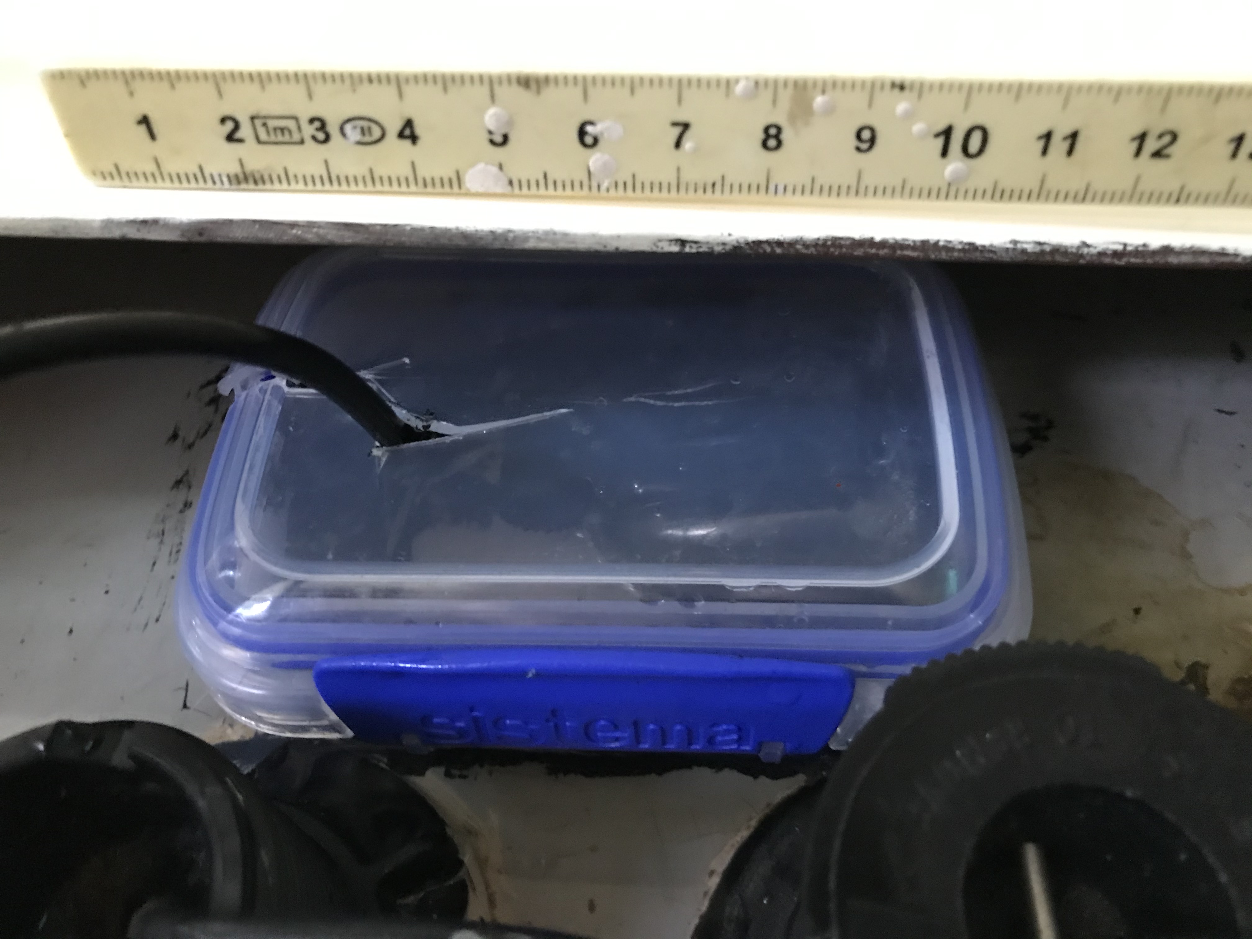
I phoned the shop I bought it from, Boating and RV in Tingalpa. Richard suggested I make a wet well inside the boat into which I should place the bullet. He suggested PVC pipe with a screw-on end, but I opted for cutting the bottom off an old Sistema clip-top food container and fixing it to the hull with FixTech 180. The clip-on top was needed to keep some water in the wet well when the boat heeled, and there was precious little room in the bilge for a larger screw-top arrangement.

I am happy to report that the wet well approach works well, and I got a nice, steady reading of a depth of 2.2m at my berth, which is what I expected (allowing for the bullet being about 0.3m to 0.5m below the waterline - I'll have to measure it more accurately). It also showed some fish, which were in no danger of being hunted by me at the time. 

So, to recap, you can use a Hook2 4x Fishfinder as an in-hull depth gauge subject to two important conditions;
  1. The hull you are shooting through is solid GRP construction, not a core-filled sandwich
  2. The bullet is placed inside a wet well inside the hull, which you will have to make, including a lid to keep the water in. A food container or sandwich box with a sealable lid will do nicely
The end result is ugly and agricultural. The plastic food container was more difficult to cut than I had anticipated. However, as we engineers say, "If it is stupid and it works, its not stupid".


Sistema food container with bottom cut off, glued to hull with FixTech 180
Wet well filled with water, bullet inserted and lid on (the lid needs to be sealed properly)

Depth gauge reading on head. Not easy to read in direct sunlight, but the head can be tilted down on its bracket.


Episode 53 Corner Blocks

 This was probably the most complex piece of wood-working I have carried out on my Cygnet 20. I had previously made up some corner-blocks, w...